Introduction
A Modbus gateway allows data to be forwarded from a Modbus RTU device to a Modbus TCP device. RS-485 is a physical layer communication standard, while Modbus is a protocol that defines how to transmit data for the application server between RTU and TCP. In this example, we will show the Modbus configuration over RS-485 of the M2M DOM series device based on an RS-485 IoT sensor.
Note: This example is based on specific prerequisites and topology. D-Link does not guarantee compatibility with all IoT sensors.
Prerequisites
1. M2M Device and IoT Sensor (Temp/Humidity) Sides:
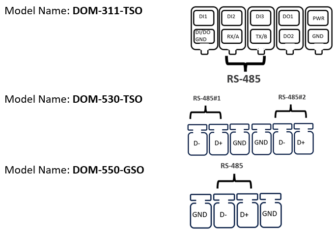
Use D+ and D- to connect DOM series products based on IoT sensors (temperature/humidity)
This feature is applicable to the following models:
2. Application Server Side:
We use the “Modbus Poll” tool for the application server and use the Ethernet local network as an example.
Note: The application server is selected by you. D-Link cannot guarantee compatible functionality.
Topology
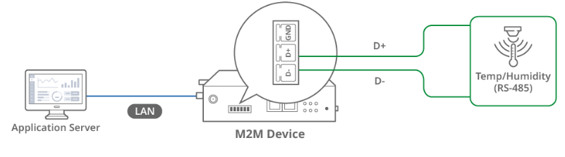
We use the DOM-530-TSO and “Modbus Poll” tool for example. The D-Link M2M DOM-530-TSO device on the left has a RS-485 interface that can connect D+ and D- to the IoT sensor.
The application server collects temp/humidity data from the IoT sensor via Modbus RTU and Modbus TCP protocols. The DOM-530-TSO Modbus Gateway allows data to be forwarded from Modbus RTU to Modbus TCP.
Note: Before starting this configuration, please make sure the basic network settings of D-Link M2M device are configured properly.
Configuration
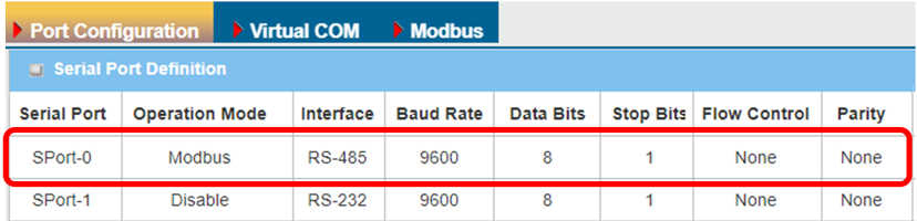
1. RS-485 Port Configuration:
Go to Field Communication > Bus & Protocol > Port Configuration tab
Please set the RS-485 baud rate according to the IoT sensor specification.
| Item | Description |
|---|---|
| Serial Port | Displays Port-0 of the RS-485 interface |
|
Operation Mode |
Displays the Modbus mode |
| Interface | Select the RS-485 physical interface for connecting to access device with the same interface specification |
| Baud Rate |
Select the appropriate baud rate for serial device communication RS-485 can use higher baud rate for 9600. Baud rate depends on the cable length and the installed environment, the longer the cable, the lower the baud rate. |
| Data Bits | Select 8 or 7 for data bits |
| Stop Bits | Select 1 or 2 for stop bits |
| Flow Control |
Select None / RTS, CTS / DTR, DSR for Flow Control in RS-232 mode Flow Control support depends on the model purchased |
| Parity | Select None / Even / Odd for Parity bit |
| Save | Click the Save button to save settings |
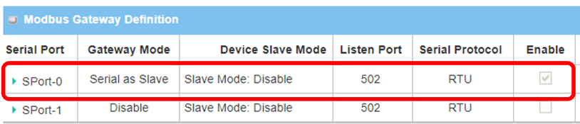
2. Modbus configuration:
Go to Field Communication > Bus & Protocol > Port Configuration tab
Please set the Listen Port and Slave mode according to the IoT sensor specification.
| Item | Description |
|---|---|
| Serial Port | Displays the SPort-0 of the RS-485 interface |
|
Gateway Mode |
Serial as Slave: Select this when the attached serial devices are all Modbus Slave devices |
| Device Slave Mode | Disable. The M2M device does not require slave-mode data checking. |
| Listen Port |
Use 502 port for the listen port Value Range 1 ~ 65535 |
Test Result
Please configure the device according to the above environment, then validate to ensure everything works as expected.
1. Expected Test Results:
The application server collects temp/humidity data from IoT sensor via Modbus RTU and Modbus TCP protocols. The DOM-530-TSO Modbus Gateway allows data to be forwarded from Modbus RTU to Modbus TCP.
2. Test Results:
We take the DOM-530-TSO and the Modbus Poll tool as an example to conduct the following test. On the DOM-530-TSO, we set the IP and port on Modbus Poll. 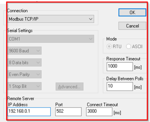
The application server collects temp/humidity data from the IoT sensor via Modbus RTU and Modbus TCP protocols. This is the test result of temperature and humidity data collected on Modbus Poll. 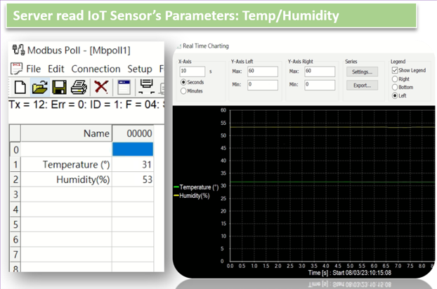
Note: In this example, we use an Ethernet local network and an application server to collect data.